How to Make Standard Addition Graph Given Volume Added Potential Readings
The number of ions belonging to various elements in a sample reveals a particular narrative. In foods and beverages, certain limits for various ions are established to protect wellness and guarantee a minimum food content. In soil and ecology water sources, heightened levels of specific heavy metallic ions tin bespeak a pollution upshot has taken place.
In the ultrapure water employed in multiple manufacturing processes, the existence of any ions beyond a certain limit suggests either the source water is unsuitable for use or that the filter system needs maintenance. At that place are many methods of ion measurement, e.g., ion chromatography (IC), inductively coupled plasma optical emission spectrometry (ICP-OES), or atom assimilation spectroscopy (AAS).
All of these are well-proven, broadly applied methods in analytical laboratories. Nevertheless, the preliminary costs are quite high. In comparison, ion measurement employing an ion-selective electrode (ISE) is a promising replacement of these expensive methods. This article describes the challenges which may be faced when using standard addition or straight measurement and how to resolve them to encourage conviction in analysts with this kind of analysis.
Introduction
In 1889, Walther Nernst created the Nernst equation, which encouraged the possibility of the evolution of pH measurement past potentiometric sensors. For approximately 70 years, pH decision was the merely analysis in which this equation was of significance. At the start of the 1960s, information technology was noticed that cuts of lanthanum fluoride crystals demonstrated superb selectivity for fluoride ionsi–2.
As such, the outset ion-selective electrode next to the pH electrode was constructed. Post-obit this, ion-selective electrodes were slowly cultivated by finding new crystal, glass, gas permeable membrane, and polymer materials. Some of these diverse ISEs are cited in Table 1.
Table 1. Overview of contrasted ion-selective electrodes and their capabilitiesiii.
| Membrane Material | Ions |
|---|---|
| Crystal | Ag+, Cu2+, Lead2+, Br-, Cl-, CN-, F-, I-, S2- |
| Polymer | Ca2+, One thousand+, Na+, Surfactants, NO3 - |
| Drinking glass | Na+, H+ |
| Gas permeable membrane | NHfour + |
Completing measurements with ion-selective electrodes may sometimes be difficult, merely when some crucial points are measured, specific ions of interest can be analyzed easily. In the subsequent sections of this commodity, general tips for potentiometric ion measurement are offered, in add-on to specific ones for basic improver and directly measurement.
Full general Suggestions
Ion measurement is uncomplicated to carry out. The manufacturer's instructions have to be followed to guarantee both long-term user satisfaction and the precision of the analysis. The subsequent points provide an outline of some common questions and problems
Consequently, it is advised to measure in the linear region to proceeds authentic and reproducible outcomes. Despite this, an ion concentration measurement in the non-linear (flattened) area by direct measurement is feasible if the sensor is calibrated in this narrow range. Electrodes usually accept a measuring range between 10-6 to ane mol/L.
The measuring range might extend up to viii mol/50 and down to ten-8 mol/L, depending on the sort of ion-selective electrode used. Prior to choosing ion measurement as the selected approach, the annotator needs to be certain that the electrode tin can measure in the concentration range of the sample.
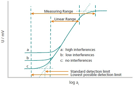
Figure 1. This illustration explains how the measuring range and the linear range are defined. The measuring range is divers from the 2 points located in the high and depression concentration range where no potential change is observed anymore. This ways either the concentration is also low, or the sensor is saturated. The linear range is defined as the range where the signal evolves linearly with the activity (concentration) of the ion according to Nernst. Image Credit: Metrohm AG
Interfering Ions
The pH electrode was the first ion-selective electrode created. This electrode displays a superb linear range of xiv decades and is selective for H+. Conversely, almost other ion-selective electrodes are non that selective for the measuring ion. There are 2 distinct kinds of interfering ions: reversible and irreversible. Irreversible interfering ions connect to the membrane material and react with it, or they produce complexes and precipitate with the measuring ion, so it is unavailable for additional analysis.
The presence of the irreversible interfering ion should be avoided if information technology is reactive towards the membrane; if not, the ISE will be destroyed. Reversible interfering ions showroom cross-sensitivities because of their comparable size and electronic properties as the measuring ion. These tin can also bind to the membrane fabric and contribute to the signal, giving erroneous outcomes. As cross-sensitivities are widespread in ion measurement, the Nernst equation was expanded to the so-called Nikolsky equation:
U = U0 ± ((two.303 × R × T) / (n × F)) × log(ai + Σkij× aj nm)
U: measured potential between ISE and reference electrode in mV
U0: measured potential betwixt ISE and reference electrode at c(ion) = 1 mol/L in mV
R: universal gas constant (R = 8.314 J/(mol∙M))
T: temperature in Kelvin
F: Faraday abiding (96485 C/mol)
due north: electrical charge of the ion
ai: activity of the ion to be measured
kij: selectivity constant (ion to exist measured / interfering ion)
aj: activity of interfering ion
m: electronical charge of the interfering ion
Currently, this equation is employed in nigh ion meters for direct measurement.
Conditioning of the Electrode
Ion-selective electrodes are unremarkably supplied dry out, separate to the membrane textile used. To activate the measuring membrane, the electrode must first be conditioned. Conditioning guarantees that the equilibrium of the measuring ion in the membrane is preserved, and as such, an verbal measurement is feasible. It is proposed to employ an ion standard solution and a concentration of c(ion) = 0.01 mol/50 as the conditioning solution.
Because consequent ion measurements need a steady equilibrium of the measuring ion in the membrane, the ISE must additionally exist conditioned in between measurements. In this instance, the workout solution is dependent on the concentration of the measuring ion inside the sample. Boosted information concerning the appropriate conditioning solution is located in the manufacturer documentation for item ion-selective electrodes or applications.
Total Ionic Strength Adjustment
The total ionic strength adjustment is necessary because the ion measurement is not dependent on the concentration of the measuring ion in solution but on the activity from then. This parameter differs with the concentration of ions within the solution and additionally with the pH, which impacts the dissociation of certain molecules.
Consequently, as an absolute minimum, a constant ionic background must be maintained, which can exist accomplished by adding ionic strength adjuster (ISA). Bailiwick to the measured ion, a stock-still pH value is required likewise. In that case, a total ionic forcefulness aligning buffer (TISAB) is employed.
ISA and TISAB solutions are usually comprised of quite a big concentration of salt, which does not bear upon the measurement. Suggestions for particular ISA and TISAB solutions are located online or in the manual provided for the ion-selective electrode.
Tabular array two. Examples of ISA/TISAB solutions for different ionic measurements and information regarding where to notice the analysis procedure.
| Ion to be measured | ISA/TISAB for 100 mL solution | Further information near procedure |
|---|---|---|
| Fluoride (F-) | 0.45 k CDTA (Komplexon IV) suspended in deionized water and dissolved with c(NaOH) = x mol/L 5.84 g NaCl 5.75 mL glacial acetic acrid | Metrohm Application Message 082 |
| Potassium (K+) | 0.584–5.844 m NaCl depending on Yard+ concentration (c(NaCl) = 0.1–1 mol/L) | Metrohm Awarding Bulletin 134 |
| Sodium (Na+) (Glass membrane) | 12.11 g Tris(hydroxymethyl)aminoethane (c(Tris(hydroxymethyl)aminoethane) = i mol/L) or vii.l mL Triethanolamine | Metrohm Application Bulletin 083 |
| Sodium (Na+) (Polymer membrane) | 14.70 g CaCl2 · 2 HiiO | Metrohm Application Bulletin 083 |
| Ammonium (NH4 +) | xl thou NaOH (c(NaOH) = 10 mol/L) | Metrohm Application Bulletin 133 |
Cleaning of the Electrode
Following every measurement, the electrode is done fully using deionized water. As they may shorten the lifetime for ion-selective electrodes with crystal membranes and destroy ion-selective electrodes with polymer membranes, organic solvents should non be used for cleaning. When measuring in very small concentration samples, the electrode must be permitted to stand for ten minutes in deionized h2o or ISA / TISAB before commencing the next measurement. If not, the ions spring to the electrode membrane material from the erstwhile measurement may lengthened out and therefore falsify the signal and the caused consequence of subsequent samples.
The deionized h2o should be swapped prior to every measurement, as diffusion can pb to an comeback in concentration of the measured ion and, consequently, contagion of the deionized water.
Storage of the Electrode
The electrode's storage requirements depend on the time menses of storage and the kind of the electrode (Table 3).
Table three. Recommendations for the storage of different ISE types.
| Membrane material | Short storage catamenia | Long storage period |
|---|---|---|
| Polymer | Dry out | Dry |
| Polymer, combined | In c(ion) = 0.01–0.1 mol/L | Dry, with some residual wet |
| Crystal | In c(ion) = 0.one mol/L | Dry, with protective cap |
| Glass | In c(ion) = 0.i mol/50 | In deionized h2o |
Electrode Lifetime
The lifetime of an ISE is dependent on the membrane blazon, sample matrix, and electrode maintenance. Satisfactory electrode maintenance is comprised of frequent cleaning, appropriate conditioning, and storage, as previously explained in this commodity. Additionally, it is essential to bandy the electrolyte of the reference electrode frequently.
As previously stated, the sample matrix can react with the membrane of the ion-selective electrode. The manual of the electrode typically details substances that should be avoided. For example, organic solvents may destroy the polymer membrane of ISEs, or acetate will disturb the crystal of the lead ISE.
For ion-selective electrodes with a crystal membrane, the membrane tin be regularly revitalized by polishing information technology. The right polishing cloth and technique can usually be located in the ISE manual3. With practiced upkeep and without lasting sample matrix influences, these kinds of electrodes can suffer numerous years of use in the laboratory. The lifetime of polymer membrane electrodes is restricted when compared to those with crystal membranes.
Over time, the polymer membrane ages, causing a loss of performance. This type of ISE typically has a "best before" engagement, through which they provide their optimal operation. The electrode should be used until this date, and following this, Metrohm can guarantee such performance for a further half dozen months. Typically, the mean lifetime for polymer membrane electrodes with typical laboratory apply is around six months. The electrode must be handled carefully; the membrane must not be touched with blank fingers because a eolith of fatty film or sweat from the skin may have a negative impact on the performance of the electrode.
Measuring Modes
Potentiometric ion measurement can be completed in two distinct methods: either by standard improver or by straight measurement. Both of these measuring principles have benefits and drawbacks, which are displayed in Tabular array 4 for ease of comparison. Past being enlightened of the properties of a sample and the frequency of analysis, the correct analysis method may exist selected appropriately.
Standard Improver
For ion measurement by standard add-on, the sample is beginning pipetted into a beaker, then ISA/TISAB is added and then numerous increments of standard are too added. Following every addition, the potential is recorded. Subsequently this, the ion concentration is calculated iteratively from the prospective difference and volume increment via the method of to the lowest degree squares. 2 kinds of standard additions are common. Either specified amounts of standard are inserted into the sample, or the device itself automatically increases the respective corporeality of standard until a difference in potential, which is previously defined, is accomplished. The second blazon of standard add-on (defined possible difference) is brash, as information technology offers more dependable results.
Table four. Advantages and disadvantages of standard addition and direct measurement.
| Standard improver | Direct measurement |
|---|---|
| Advantages | |
|
|
| Disadvantages | |
|
|
Ion measurement by standard addition is selected equally soon as the matrix is unknown and might include interfering ions that brand up part of the measured bespeak. The full volume of standard added should exist between 10 and xc% of the buret book, and the corporeality of additions should be 4 at least (Figure 2). Refilling of the buret must non occur. The additional volume should not surpass 25% of the sample volume, or else dilution will alter the result. Furthermore, there should not exist temperature differences between the standard solution and sample solution. The possible difference is also a crucial bespeak to take into consideration. It is intended to add equally much standard every bit necessary to achieve a voltage difference of at minimum 12 mV per addition. The calculation of the event is completed iteratively past the device itself.
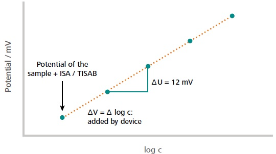
Figure ii. Case of a typical standard add-on curve. The first measuring point corresponds to the measured potential of the sample solution (including auxiliary solutions). The subsequent measuring points correspond to the measured potential later on each addition of the standard. The initial concentration of the sample is calculated from the measured potential difference in dependence of the added volume increment. The dilution of the sample past auxiliary solutions is considered in the calculations as well. Paradigm Credit: Metrohm AG
If the outcome is not reproducible, the following points must be examined:
- Is the dosing unit tight?
- How much standard is dosed per improver?
- Does the potential measurement betwixt the additions reach a stable potential?
- Is the solution stirred while calculation standard?
- Are in that location air bubbles in the tubing?
- Is the caused slope inside acceptable limits?
Direct Measurement
This kind of ion measurement is washed if the sample matrix includes only a small number of interfering substances and is comparable for all samples. Furthermore, samples that include small concentrations of the ion are more than appropriate for analysis via straight measurement. These samples create issues with measurement past standard addition: the curve flattens and the evaluation cannot exist carried out appropriately (non-linear range).
To ascertain the concentration of the ion in the sample, a calibration must previously be made. The calibration standard concentrations should be selected in such a way that they cover the anticipated concentration of the ion in the sample. The scale standards are comprised of a specific concentration of the measuring ion in addition to the same proportion of deionized water to ISA/TISAB that is employed post-obit this in the determination itself.
The standards must be measured from the smallest to the largest concentration to lessen the impact of acquit over. The analysis is carried out by pipetting the standard into a beaker, adding the corresponding quantity of ISA/ TISAB, and submerging the sensor. The outcome is and so shown directly in the called concentration unit of measurement. Because the dilution produced past adding ISA/TISAB must non be overlooked.
Should the results be non-reproducible, the following points can be examined:
- Is the same ratio of ISA/TISAB to sample/standard plus h2o applied for the standard and sample measurements?
- Is the corporeality of ISA/TISAB equal for each of the standards and for the measuring solution?
- Is the caused slope of the calibration acceptable?
- Were the standards measured in the right/defined order?
- Was the electrode properly conditioned between measurements?
- Does the calibration range fairly cover the sample concentration range?
General Points to Consider for Ion Measurement
- Is the standard newly prepared? Some standards can modify their concentration over time.
- What is the historic period of the electrode? Polymer electrodes in particular age quickly. Metrohm recommends a maximum shelf life of 2 years, dependent on the type of electrode.
- What about the measured value drift? A drift of 1 mV/min at nigh should be applied.
- Was the sensor appropriately conditioned? If not, the betoken and the corresponding results tend to drift.
- The electrode may exist tested by immersing the sensor in c(ion) = ane ∙ ten-four mol/L and c(ion) = 1 ∙ 10-iii mol/50. If the difference in voltage relates to at least 47.iii/z* mV (at 25 °C) (80% of the Nernst Slope), where z* is the charge of the ion, and so the electrode is ok and tin can be used.
Summary
Potentiometric ion measurement by standard addition or by direct measurement is a great option in place of more expensive procedures such as AAS, ICP-OES, or IC. The determination is dependable and quick when respecting the terms of storage, planned employ, and measuring range.
References and Further Reading
- Oehme, F. Ionenselektive Elektroden, Grundlagen und Methoden der Direktpotentiometrie; Dr. Alfred Hüthig Verlag GmbH: Heidelberg, 1986.
- Cammann, K. and Galster, H. Das Arbeiten mit ionenselektiven Elektroden - Eine Einführung für Praktiker; Springer-Verlag: Berlin, Heidelberg, New York, 1996.
- Metrohm AG. Ion-selective electrodes (ISE), Metrohm AG: Herisau, Switzerland, 2015. 8.109.8042EN

This information has been sourced, reviewed and adjusted from materials provided by Metrohm AG.
For more information on this source, please visit Metrohm AG.
Source: https://www.azom.com/article.aspx?ArticleID=19867
0 Response to "How to Make Standard Addition Graph Given Volume Added Potential Readings"
Post a Comment